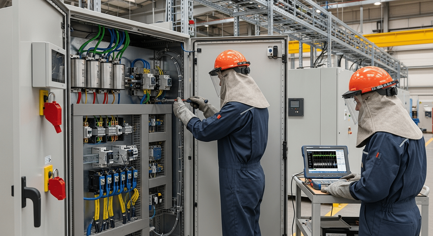
Every year, unplanned equipment failures cost industrial facilities millions in lost production, emergency repairs, and safety incidents—yet most of these failures broadcast warning signs weeks before they happen. Predictive maintenance infrared scanning transforms how maintenance teams protect critical equipment by detecting invisible temperature anomalies that signal developing problems. This non-invasive technology identifies electrical faults, mechanical wear, and insulation failures before they cause catastrophic breakdowns.
Delta Wye Electric has provided infrared inspection services to manufacturers and critical facilities since 1980, helping operations teams prevent costly downtime through proactive thermal imaging programs. Understanding how to implement and optimize infrared scanning for predictive maintenance starts with grasping the fundamental technology and its applications across your facility’s critical systems.
What Is Predictive Maintenance Infrared Scanning?
Predictive maintenance infrared scanning is a non-contact inspection method using thermal cameras to detect temperature anomalies in equipment. It identifies developing problems like electrical resistance, mechanical friction, or insulation breakdown by capturing heat patterns invisible to the naked eye, enabling repairs before failure occurs.
This technology works because all equipment generates heat during operation. When components begin to fail, they produce abnormal thermal signatures—loose electrical connections create resistance and heat, worn bearings generate friction, and degraded insulation allows heat to escape. Infrared cameras capture these temperature variations, converting invisible infrared radiation into visible thermograms that maintenance teams can analyze.
Common problems detected through infrared scanning include:
- Electrical loose connections and corroded terminals
- Overloaded circuits and unbalanced loads
- Bearing failures and misaligned couplings
- Motor winding problems and overheating
- Insulation degradation in electrical and mechanical systems
- Fluid leaks in hydraulic and compressed air systems
- HVAC inefficiencies and building envelope issues
The severity of detected problems correlates directly with temperature rise above normal operating conditions:
| Temperature Rise | Risk Level | Recommended Action |
|---|---|---|
| 10-20°F above baseline | Low | Monitor during next inspection cycle |
| 21-40°F above baseline | Moderate | Schedule repair within 30-60 days |
| 41-75°F above baseline | High | Schedule immediate repair |
| >75°F above baseline | Critical | Shut down and repair immediately |
Your facility’s infrared inspection program becomes a cornerstone of reliability when implemented systematically. Regular thermal imaging transforms reactive maintenance into proactive asset management, catching problems while they’re still manageable and cost-effective to fix.
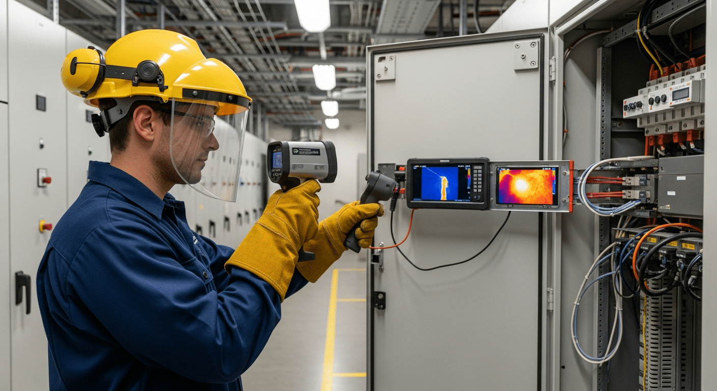
How Infrared Thermography Works for Equipment Monitoring
Infrared thermography for predictive maintenance follows a straightforward process that converts heat energy into actionable maintenance data. Every object above absolute zero emits infrared radiation proportional to its temperature. Thermal cameras detect this radiation through specialized sensors, then sophisticated software converts the energy readings into temperature measurements displayed as color-coded thermograms.
The inspection process follows these essential steps:
- Equipment emits infrared radiation based on operating temperature
- Camera sensor detects radiation across its field of view
- Software converts radiation intensity to temperature data
- Thermogram displays heat patterns using color gradients
- Analysis identifies temperature anomalies against baselines
- Maintenance teams prioritize repairs based on severity
Understanding key thermography concepts ensures accurate inspections:
- Emissivity: Different materials emit infrared radiation at different rates. Shiny metals have low emissivity while painted surfaces have high emissivity, affecting temperature readings.
- Reflected Temperature: Surrounding heat sources can reflect off equipment surfaces, creating false readings that experienced thermographers must account for.
- Thermal Gradient: Temperature differences across components indicate heat flow patterns and potential problem areas.
- Baseline Comparison: Comparing current readings to historical data reveals developing issues before absolute temperatures reach critical levels.
Frequently Asked Questions About Infrared Inspections
How often should infrared inspections be performed?
Critical equipment requires quarterly inspections, while general electrical systems benefit from annual thermographic surveys. Increase frequency for aging equipment or harsh operating environments.
What equipment requires infrared scanning?
Any equipment generating heat during operation benefits from thermal imaging—electrical panels, motors, bearings, steam systems, hydraulics, and building envelopes all reveal problems through temperature anomalies.
Can infrared detect all equipment problems?
Thermal imaging excels at detecting problems that generate heat but cannot identify issues without thermal signatures, such as loose mechanical fasteners at ambient temperature or internal electrical faults not yet producing heat.
What’s the difference between qualitative and quantitative thermography?
Qualitative inspections identify hot spots and temperature patterns for comparison, while quantitative analysis measures exact temperatures to calculate severity and determine specific failure modes.
Essential Equipment and Tools for Infrared Predictive Maintenance
Building an effective infrared scanning program requires selecting appropriate equipment for your facility’s specific applications. Camera resolution directly impacts detection capability—higher resolution reveals smaller temperature anomalies at greater distances, critical for inspecting equipment from safe working distances.
| Application | Minimum Resolution | Recommended Resolution | Temperature Range |
|---|---|---|---|
| Electrical Panels | 160×120 | 320×240 | -4°F to 752°F |
| Rotating Equipment | 320×240 | 640×480 | 32°F to 1202°F |
| Building Envelope | 160×120 | 320×240 | -4°F to 248°F |
| High-Temperature Process | 320×240 | 640×480 | 32°F to 2732°F |
Essential accessories enhance inspection accuracy and safety:
- Reference temperature sources for calibration verification
- Protective infrared windows for energized electrical equipment
- Mounting equipment for fixed installations monitoring critical assets
- Analysis software for trending and report generation
- Reporting tools for documenting findings and tracking repairs
Budget considerations shape program development. Entry-level cameras costing several thousand dollars provide basic detection capabilities suitable for routine inspections. Professional-grade equipment offers higher resolution, better sensitivity, and advanced features like radiometric video recording—worthwhile investments for facilities with extensive critical equipment. Many operations combine in-house basic screening with periodic professional inspections using high-end equipment.
Your infrared program integrates with other predictive technologies. Combining thermal imaging with power quality analysis provides comprehensive electrical system diagnostics, catching both thermal and electrical anomalies before failure.
Applications Across Industrial Systems
Infrared scanning applications span every industrial system generating or transferring heat. Each application requires specific inspection techniques and interpretation criteria based on equipment type and operating conditions.
Electrical Applications
Electrical systems represent the most common infrared inspection targets. Switchgear, transformers, and motor control centers develop hot spots from loose connections, overloading, or component degradation. Power distribution systems reveal unbalanced loads and failing components through comparative thermography—comparing phases should show similar temperatures under balanced conditions. Circuit breakers display characteristic thermal patterns when approaching capacity limits or experiencing internal degradation.
Mechanical Applications
Rotating equipment provides clear thermal signatures of developing problems. Motors show winding problems through uneven heat distribution across the housing. Bearings approaching failure generate excess heat from increased friction. Gearboxes reveal lubrication issues and gear wear through abnormal temperature patterns. Pumps indicate seal failures and cavitation through thermal anomalies. Compressors display valve problems and efficiency losses through temperature variations. Conveyor systems show belt tension issues and roller bearing failures before audible or visible symptoms appear.
Building Systems
Facility infrastructure benefits from regular thermal surveys. Roof moisture intrusion appears as temperature differences during thermal cycling. Insulation gaps create obvious thermal bridges in building envelopes. HVAC performance issues manifest through abnormal temperature distributions in ductwork and equipment. Steam traps failing open or closed produce distinct thermal signatures that quantify energy losses.
Each application requires appropriate inspection intervals based on criticality and failure consequences. Your industrial power distribution systems might need quarterly inspections while building envelope surveys occur annually. Document baseline readings for all equipment to enable trend analysis and early problem detection.
Implementing Your Infrared Scanning Program
Successful predictive maintenance using infrared scanning follows a structured implementation approach. Start by defining critical assets—equipment whose failure would significantly impact production, safety, or compliance. These assets receive priority for baseline establishment and frequent monitoring.
Your implementation checklist ensures comprehensive program development:
- Define critical assets based on failure impact and replacement cost
- Establish baselines through initial thermographic surveys under normal operating conditions
- Set inspection intervals based on criticality, with quarterly inspections for vital equipment
- Create procedures documenting inspection routes, camera settings, and safety requirements
- Train personnel in basic thermography principles and equipment operation
- Document findings using standardized reports with images, temperatures, and recommended actions
- Track metrics including problems detected, failures prevented, and program costs versus savings
Program success factors determine long-term effectiveness:
- Management support ensures resources and priority for inspections
- Qualified thermographers provide accurate data collection and interpretation
- Consistent procedures enable trending and comparison across inspections
- Trending analysis reveals degradation patterns before absolute temperatures reach critical levels
- Integration with CMMS streamlines work order generation and tracks repair completion
Avoid common implementation mistakes that undermine program value. Insufficient training leads to missed problems or false positives. Inconsistent inspection conditions prevent meaningful trending. Delayed repairs negate early detection benefits. Poor documentation prevents knowledge transfer and continuous improvement.
Your program benefits from industrial controls and automation integration. Fixed thermal cameras monitoring critical equipment provide continuous temperature data, alerting operators to developing problems between manual inspections.
Interpreting Thermal Images and Taking Action
Accurate thermal image analysis transforms colorful pictures into actionable maintenance intelligence. Temperature delta—the difference between suspected problem areas and reference points—provides the primary indicator of severity. A 40°F rise above ambient on an electrical connection demands different response than the same rise above normal operating temperature on a bearing.
Interpretation requires considering multiple factors simultaneously. Load percentage affects expected temperatures—equipment at 50% capacity runs cooler than at full load. Environmental conditions influence readings through ambient temperature, wind, and solar loading effects. Equipment history provides context for determining if temperatures are increasing over time.
Your priority matrix guides response decisions:
- Temperature rise below 20°F + Non-critical equipment + Low load = Monitor at next scheduled inspection
- Temperature rise 20-40°F + Critical equipment + Normal load = Schedule repair within 30 days
- Temperature rise above 40°F + Any criticality + Any load = Immediate investigation and repair planning
Follow-up actions vary by severity and equipment type. Minor issues might only require monitoring during regular inspections. Moderate problems need scheduled repairs during planned outages. Severe anomalies demand immediate intervention to prevent catastrophic failure.
Common Interpretation Challenges
What causes false thermal readings?
Reflections from nearby heat sources, incorrect emissivity settings, and extreme viewing angles create misleading temperature measurements. Experienced thermographers recognize and compensate for these effects.
How do environmental factors affect readings?
Wind cools equipment surfaces, solar loading adds heat, and rain dramatically changes surface temperatures. Schedule inspections during stable conditions when possible, or note environmental factors for future comparison.
When should you call in certified thermographers?
Complex problems, critical equipment assessments, and insurance or compliance inspections benefit from Level II or III certified thermographers. They provide detailed analysis and authoritative documentation for important decisions.
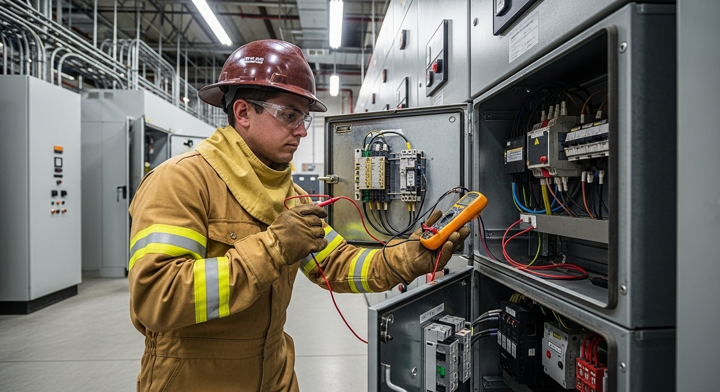
Safety considerations guide all thermal inspections. Arc flash studies and compliance requirements determine safe working distances and PPE requirements for electrical inspections. Certified electricians should perform any repairs on energized equipment following proper safety procedures.
ROI and Cost Justification
Infrared scanning programs deliver measurable returns through multiple value streams. Understanding these benefits helps justify initial investment and ongoing program costs to management.
Cost factors include both one-time and recurring expenses. Equipment investment ranges from entry-level cameras to professional systems with advanced features. Training ensures effective equipment use and accurate problem identification. Choosing between outsourcing and in-house capabilities depends on inspection frequency and available expertise.
Savings accumulate across several categories:
- Avoided downtime: Early problem detection prevents unexpected failures that halt production
- Reduced emergency repairs: Planned maintenance costs less than emergency response
- Extended equipment life: Addressing problems early prevents cascading damage
- Energy efficiency: Identifying waste reduces power consumption
- Insurance benefits: Documented inspection programs may qualify for premium reductions
| Facility Size | Annual Inspection Cost | Typical Annual Savings | Payback Period |
|---|---|---|---|
| Small (<50,000 sq ft) | $5,000-$15,000 | $15,000-$50,000 | 3-12 months |
| Medium (50,000-200,000 sq ft) | $15,000-$40,000 | $50,000-$200,000 | 3-9 months |
| Large (>200,000 sq ft) | $40,000-$100,000 | $200,000-$1,000,000 | 2-6 months |
Track specific metrics to demonstrate program value:
- Mean time between failures (MTBF) increases as problems get fixed before causing breakdowns
- Emergency work order percentage decreases as planned maintenance replaces reactive repairs
- Energy consumption drops as efficiency problems get identified and corrected
- Maintenance costs stabilize as catastrophic failures become rare
Your comprehensive services overview shows how infrared scanning integrates with other reliability initiatives. Combining thermal imaging with vibration analysis, oil analysis, and ultrasonic testing creates a complete predictive maintenance program that maximizes equipment reliability while minimizing total maintenance costs.
Key Takeaways
Infrared scanning detects equipment problems weeks or months before failure through thermal anomaly detection. This early warning system transforms maintenance from reactive firefighting into proactive reliability management. Successful programs require proper equipment, trained personnel, and systematic procedures that ensure consistent data collection and analysis. The return on investment typically materializes within the first year through prevented failures and optimized maintenance scheduling.
Predictive maintenance infrared scanning transforms reactive firefighting into proactive reliability management, protecting both your equipment investment and operational continuity. The technology’s ability to identify invisible problems before they cause failures makes it indispensable for modern maintenance programs.
Ready to implement infrared scanning at your facility? Contact Delta Wye Electric’s certified thermography team for a consultation on building your predictive maintenance program. Our four decades of experience helping facilities prevent costly downtime ensures your program starts strong and delivers lasting value.
Explore our complete range of preventive maintenance and reliability services to build a comprehensive equipment protection strategy that keeps your operation running at peak performance.